Innovative Weld Inspection and Monitoring Systems
Improve the quality of manufactured goods with highly specialized machine vision solutions for all welding applications.

Xiris Weld Monitoring Products
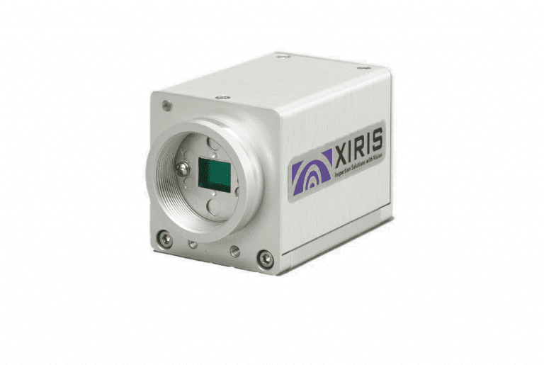
XVC-1000/XVC-1100
A fully digital weld camera intended for monitoring all open arc welding processes for OEMs, Advanced End Users or Lab Environments, featuring:
- High Dynamic Range (HDR) Images in Monochrome (XVC-1000) or Color (XVC-1100)
- Remote Monitoring from up to 100 Metres
- C/CS Mount for custom optics
- Up to 55 fps @ 1280 x 1024
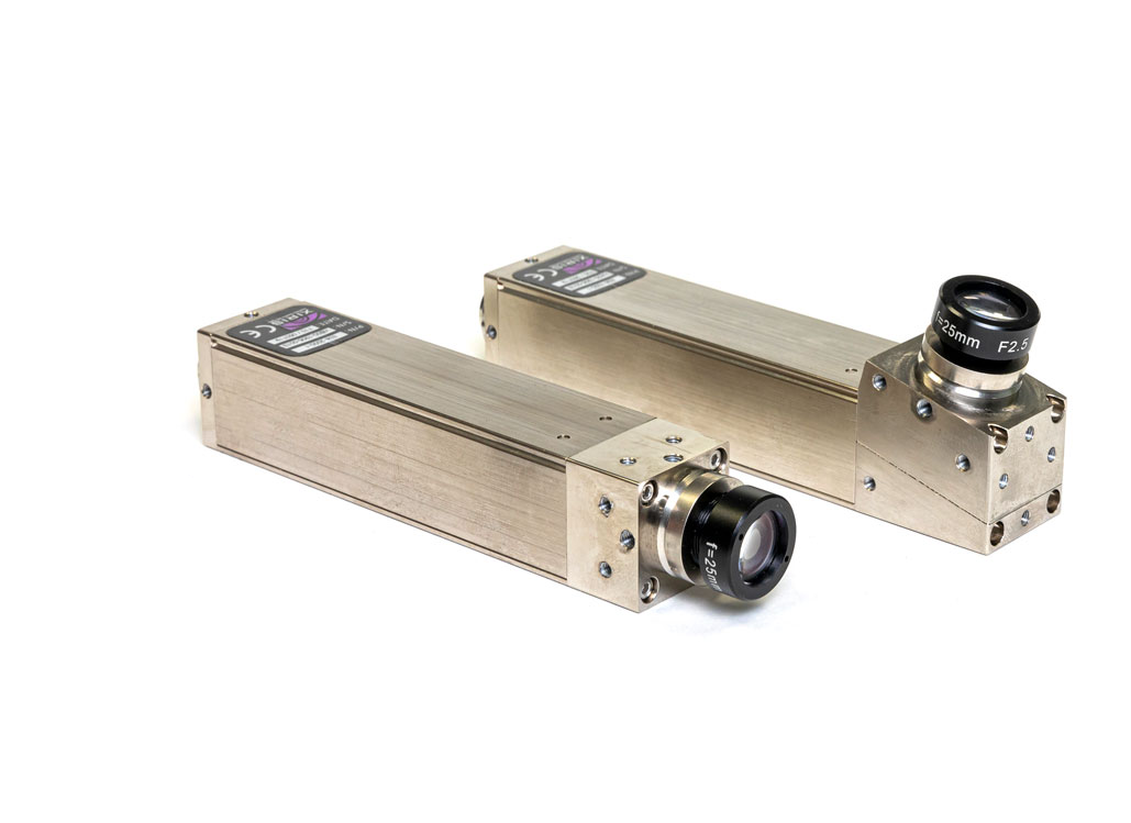
XVC-700/XVC-710
A next-generation weld camera specifically designed for integration with welding automation in spaces too small for traditional weld cameras, featuring:
- High Dynamic Range (HDR) Images in Monochrome (XVC-700) or Color (XVC-710)
- Slimline, lightweight form factor
- Broad array of compact S Mount optics and accessories
- Configurable with off-axis optics for simplified installations
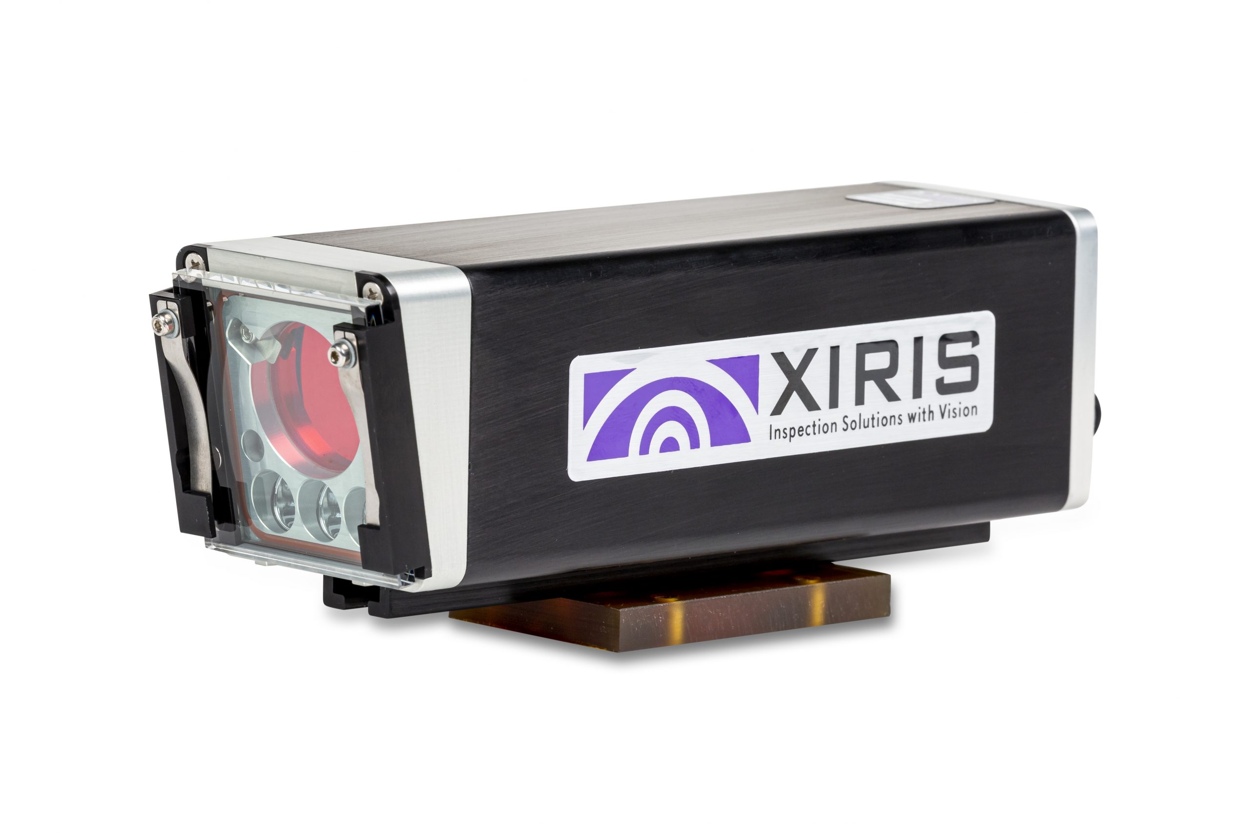
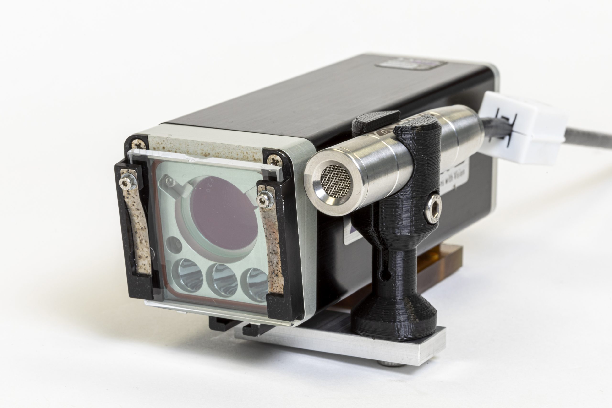
XVC-1000e/XVC-1100e
A ruggedized weld camera for production and harsh environments that can be provided as a standalone camera, or packaged as a complete system with accessories. Same base features as XVC-1000/1100 but with:
- High Dynamic Range (HDR) in Monochrome (XVC-1000e) or Color (XVC-1100e)
- IP65 rated air- or water-cooled housing
- Integrated LED lighting and optics with motorized fine focus
- Replaceable front window for spatter/smoke protection
XVC-S
Out of the box and affordable, the XVC-S is the ideal weld camera monitoring solution for submerged arc welding.
- High Sensitivity Color Camera in a rugged, air cooled housing
- Adjustable field of view
- Cross Hair Generator
- Integrated LED Light Sources
- Rugged Monitor Enclosure
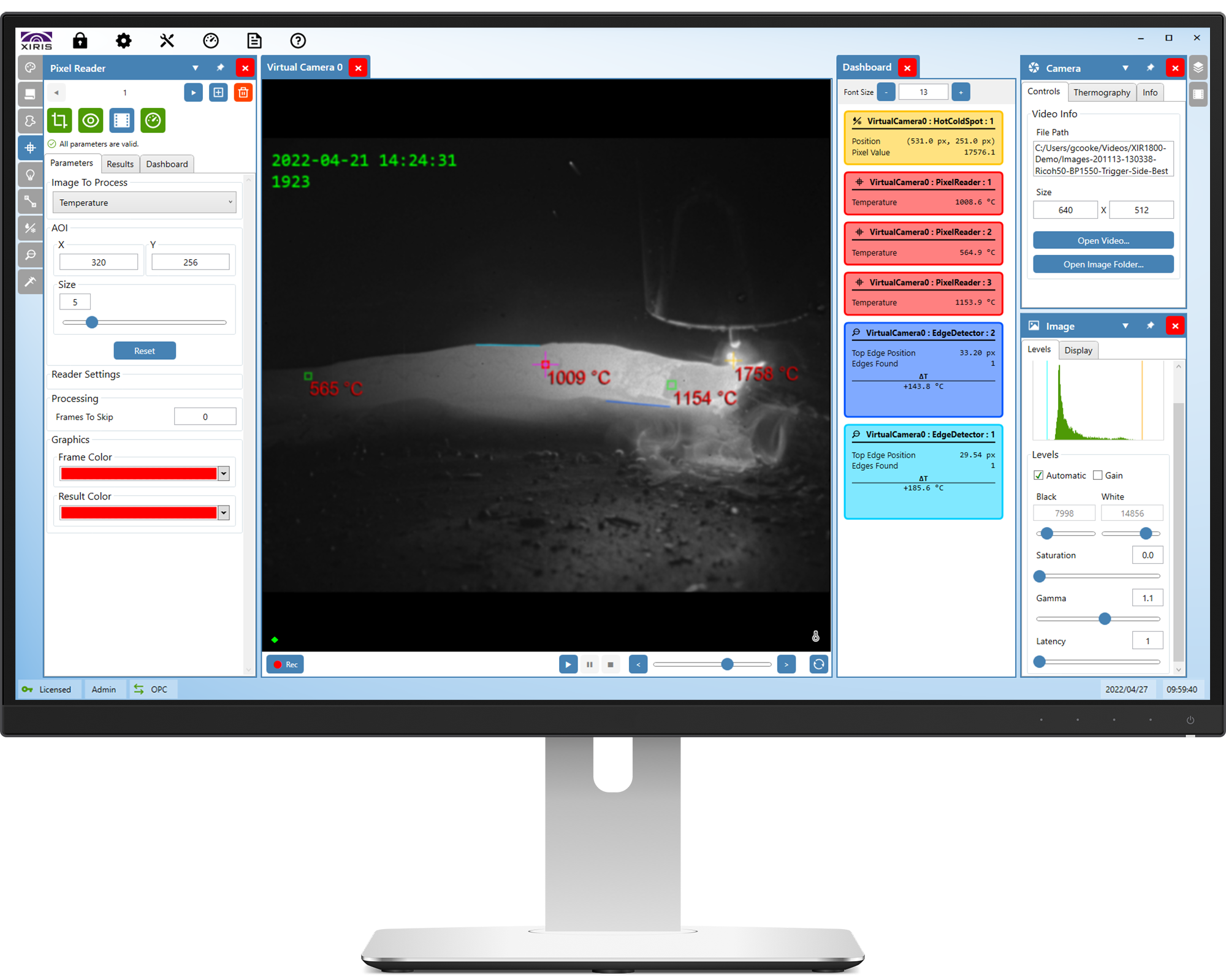
WeldStudio™ 3, WeldStudio™ 3 Pro and WeldSDK
WeldStudio™ 3 is included with purchase of all XVC weld cameras. It includes access to standard tools such as the Recipe Management system for easy and fast set-up and configuration, advance image processing, and the ability to remotely view, record, and playback welding processes.
WeldSudio™ 3 Pro is for advanced users who would benefit from machine vision and thermal measurement tools such as blob segmentation, edge, and thermal temperature reading tools. This version of the software program comes included with purchase of the XIR-1800 thermal camera.
The WeldSDK™ (software development kit) allows advanced Users and OEMs to create custom image processing & display applications for integration into welding machines.
WeldMic™
A robust welding microphone specifically designed for integration with Xiris weld cameras, allowing operators to remotely hear, record and playback welding sound to further enabling process optimisation.
Incorporating directional pickup, noise reduction electronics and 10 Band EQ, WeldMic™ provides clear audio transmission that is integrated with the welding video.
Xiris Weld Inspection Products
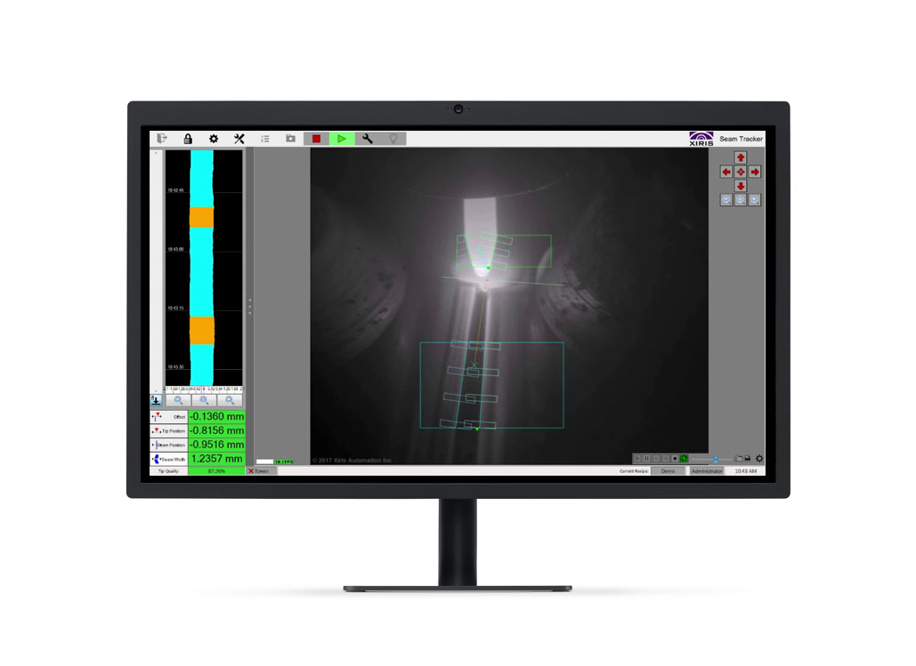
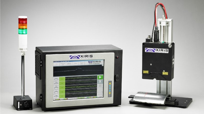
SeamMonitor™
The SeamMonitor™ system measures the alignment of the weld seam relative to the torch tip, the width of the weld seam and the torch tip condition. The system includes a Xiris open arc weld camera system, industrial HMI controller, and SeamMonitor™ software.
- Measures seam width and alignment movement history for process monitoring
- Automatically alerts the operator when out-of-tolerance weld conditions occur
- Integrates with all Xiris High Dynamic Range (HDR) cameras in monochrome or color
- Configurable optics that can be adjusted to suit most common
- welding environments
Integrates with other automation hardware and process monitoring systems
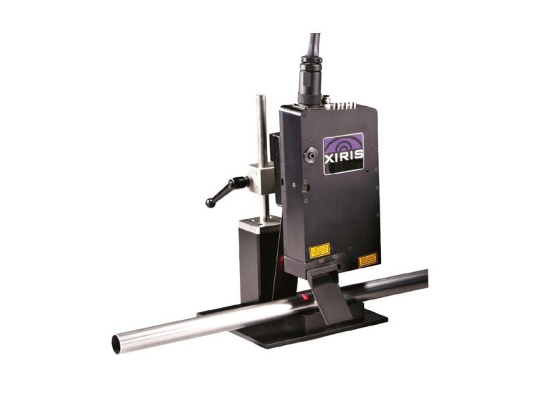
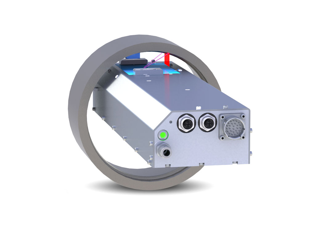
WI2200
A laser-based 3D post-weld inspection system designed to detect quality issues related to the forming, welding and scarfing processes on Tube & Pipe mills with outside diameters of 5-200 mm (0.2-8″).
- Simplify and reduce mill set up time with real-time feedback on adjustments
- Improve weld quality, with 100% in-line monitoring right at the mill
- Non-contact, non-destructive sensors do not interfere with forming, welding and scarfing process
- Reduce operating costs with lower material scrap, customer returns and product liability claims
- Improved mill efficiency with real-time process monitoring, trend reporting, warning and alarms
- Air-cooled using factory air
WI3000
A laser-based 3D post-weld inspection system designed to detect quality issues related to the forming, welding and scarfing processes on larger High Frequency Tube & Pipe mills with outside diameters greater than 13 mm (1/24″).
- Simplify and reduce mill set up time with real-time feedback on adjustments
- Improve weld quality, with 100% in-line monitoring right at the mill
- Non-contact, non-destructive sensors do not interfere with forming, welding and scarfing process
- Reduce operating costs with lower material scrap, customer returns and product liability claims
- Improved mill efficiency with real-time process monitoring, trend reporting, warning and alarms
- Rugged water-cooled sensor
BeadScan
A sensor and image processing system for scanning, inspecting and recording the back side of a first pass weld bead, typically found in large welding projects such as pipeline construction, ship building, pressure vessel manufacturing or large pipe fabrication. Featuring:
- High resolution 2D image and a 3D shape profile generation of the entire weld bead
- Low-profile design fits inside pipes with ID >200mm
- Sensor head includes a high-resolution laser triangulation system and a high resolution 2D on-axis camera with its own specialized lighting
- Intuitive, easy to use software to fully inspect, analyze, annotate and record each weld
- Integrated bead profile inspection tools for advanced defect detection