Xiris Automation
Resources
Xiris White Papers
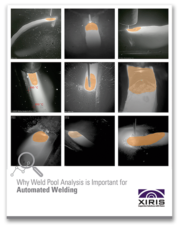
Why Weld Pool Analysis is Important for Automated Welding
Explore precise melt pool segmentation with real-world applications showcasing MeltPool AI’s effectiveness.
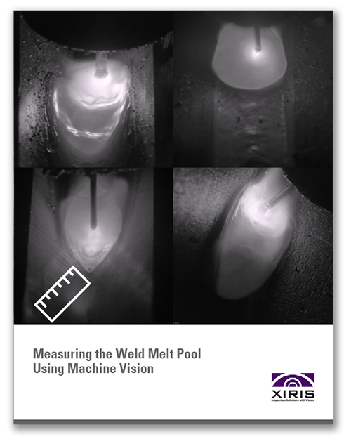
Measuring the Weld Melt Pool Using Machine Vision
Learn about the four major steps that are required when using machine vision tools to measure the weld melt pool.
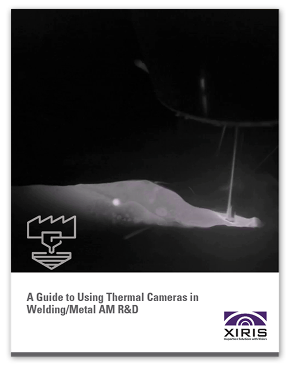
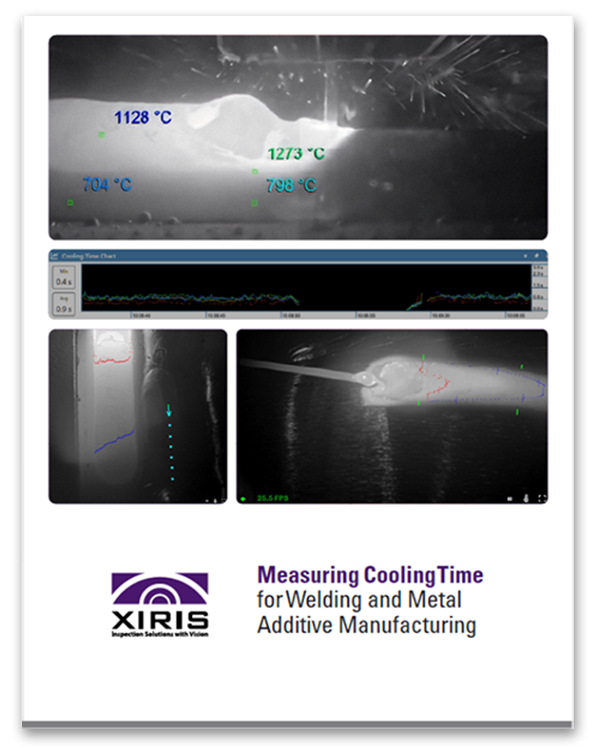
A Guide for Using Thermal Cameras in Welding and Metal AM R&D
Move beyond single-point sensors with precise cooling rates, peak temps, and AM layer measurement.
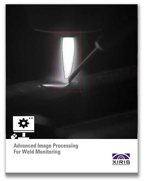
Advanced Image Processing For Weld Monitoring
Certain features can be hard to see under normal imaging conditions and can be improved with image enhancement tools.
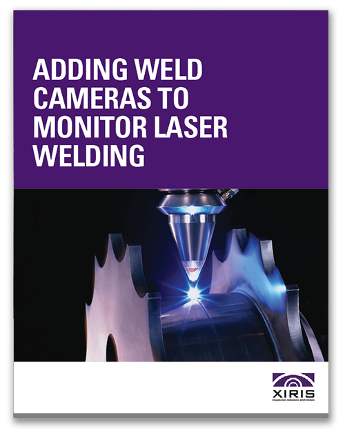
Adding Weld Cameras to Monitor Laser Welding
Learn the benefits and considerations of using weld cameras to monitor laser welding applications.
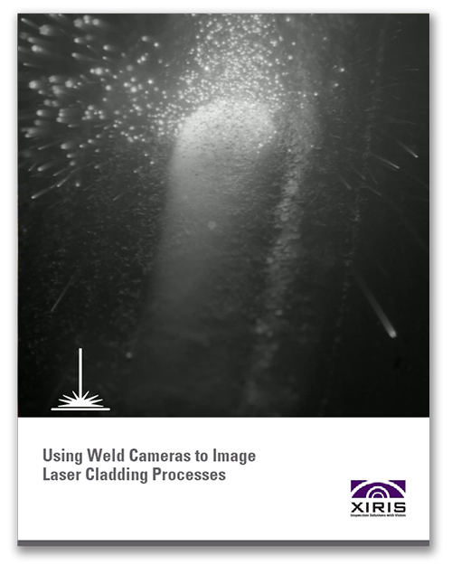
Using Weld Cameras to Image Laser Cladding Processes
Learn how the state-of-the-art process is used to produce high-performance coatings on metal parts to reduce wear or corrosion.
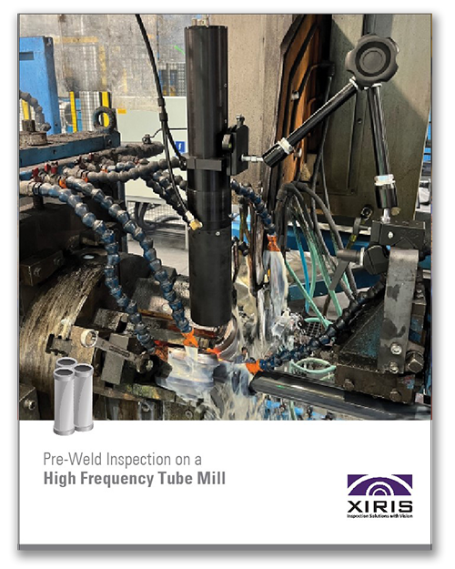
Pre-Weld Inspection on a High Frequency Tube Mill
Discover why Pre-Weld Inspection is a game-changer. Learn how it matters and why it’s crucial for your tube manufacturing process.

Metal Additive Manufacturing Like You’ve Never Seen It Before
See how HDR Weld Cameras can show operators materials in real-time during the additive process.

Justifying the Cost of Automatic Weld Inspection on a Tube Mill
This paper features Return on Investment (ROI) calculations to justify productivity investments.
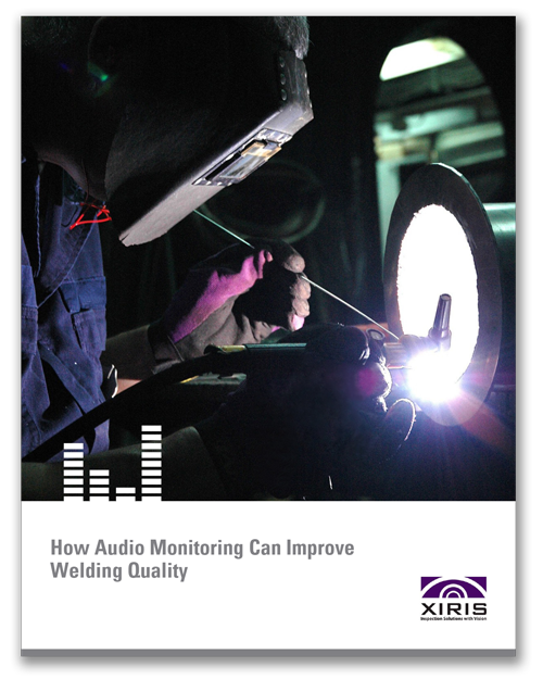
How Audio Monitoring Can Improve Welding Quality
Weld Cameras with audio capture deliver essential benefits for any manufacturer.
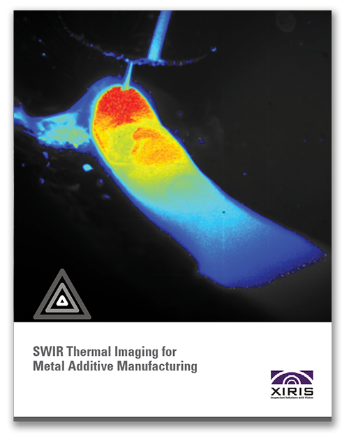
Thermal Imaging for Metal Additive Manufacturing
A review of challenges faced in AM weld detection and the benefits that SWIR thermal imaging offers.

The Xiris Glossary of Machine Vision Terminology
Machine Vision terminology is not common and well known. Use this glossary to get the full picture.
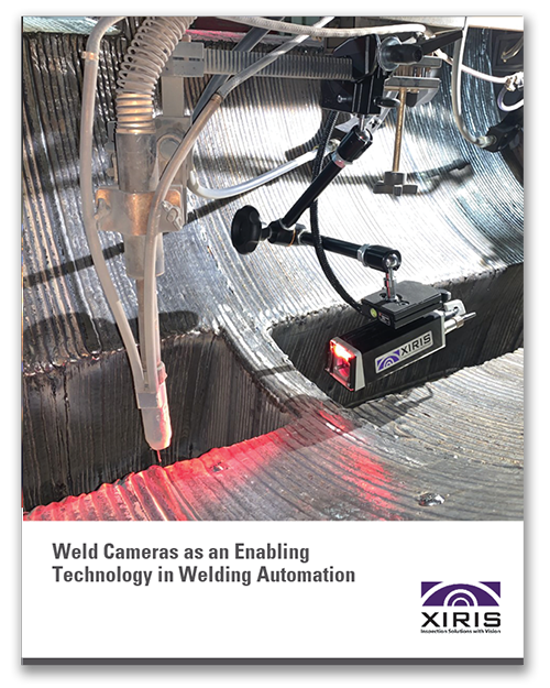
Weld Cameras as an Enabling Technology in Welding Automation
Learn how weld cameras are used to monitor critical weld parameters in both hard and flexible automation applications.

Ensuring Quality in Metal Additive Manufacturing
Learn how investing in technology to improve your Metal AM quality is a worthwhile step.

Improving Metal Additive Manufacturing Using Cameras
Improve quality and process control by generating high-contrast images and videos using HDR cameras.
The Xiris Glossary of Weld Imaging Terminology
Weld Camera terminology is unique. Use this glossary of terms to avoid confusion.

How Should Welding Education Pivot to Meet the Future?
See how technologies like weld cameras are becoming important for the future of welding education.
8 Ways to Improve Welding Productivity Using a Weld Camera
Learn eight ways to improve welding productivity using a weld camera.
Weld Camera Capabilities and Selection Checklist
Use this checklist to ensure you get best Weld Camera solution for your business.
How an Operator can Outperform Automated Laser Seam Tracker
Automated seam trackers have some significant problems when put to use in the field.
A Short History of Using Cameras for Weld Monitoring
A history of using High Dynamic Range (HDR) imaging with a video camera for monitoring welding.

Using a Weld Camera to Teach Welding Students
Weld cameras can help better train students and demonstrate new welding techniques using recorded video and playback.
Welding Like You’ve Never Seen Before
Xiris HDR cameras capture detail in the arc and background with more precision than even the human eye can deliver.
Non-Destructive Inspection of Tube and Pipe Welds
Better understand how laser-based inspection can improve weld quality and efficiency on tube or pipe mills.

Non-Destructive Inspection of Tube and Pipe Welds-Chinese
Better understand how laser-based inspection can improve weld quality and efficiency on tube or pipe mills.
Weld Cameras Mean Better Quality for Tube & Pipe Production
Tube and Pipe fabricators can benefit from real time weld monitoring using HDR cameras.
FAQ
XVC-1000/1100
What is the difference between the XVC-1000 and XVC-1100?
The XVC-1000 produces a monochrome image, while the XVC-1100 produces a color image. Additionally, you can use the serial number sticker found on the back of the camera to identify if it is either 1000 or 1100 in the Date field. (ie: 1000/071519)
How do I identify whether I have an XVC-1000 or an XVC-1100?
The serial number sticker found on the back of the camera will note either 1000 or 1100 in the date field. (i.e.: 1000/071519).
What is the standard filter combination for 1100 cameras?
The standard combination is: ND Filter (ND060-27) followed by UV+NIR Cut Filter (SP705-27) and Clear UV Filter for spatter protection (No Markings)
* If a camera is purchased with a Xiris optics kit.
* These are defaults that will work for most applications, you can modify as needed.What is the standard filter combination for 1000 cameras?
The standard combination is: Red Bandpass (BP635-27) followed by UV+NIR Cut Filter and Clear UV Filter for spatter protection (No Markings)
* If a camera is purchased with a Xiris optics kit.
* These are defaults that will work for most applications, you can modify as needed.Which lens should I use?
To choose the right lens (based on your desired working distance and field of view), please refer to Lens Configuration Chart PDF located under Resources in the Support Center.
Which aperture setting should I be using?
A good starting point is f/4.0. You can adjust the aperture to let more or less light in depending on your environment or application.
My camera is not producing an image. What should I do?
- Ensure all the cables are correctly connected. The camera has 2 green LEDs located below the RJ45 connector, which when lit, indicate connectivity.
- If the ethernet LEDs are active and there is still no camera image, check your network adapter settings to ensure that the IP address is set to automatic.
- If you are using WeldStudio™, try restarting the software. The camera will start a few moments after the software appears.
XVC-1000e/1100e
How do I identify whether I have an XVC-1000e or an XVC-1100e?
The XVC-1000e produces a monochrome image and has a red filter in front of the lens, while the XVC-1100e produces a color image and has a clear filter in front of the lens. Additionally the serial number sticker found on the top of the camera will note either 1000e or 1100e in the date field. (i.e.: 1000e/083019)
How do I change the spatter shield?
The spatter shield can be easily removed and replaced by sliding it in and out of its mount. No tools are required.
Are there different types of spatter shields available?
Are there different types of spatter shields available?
Yes. Xiris offers both a borosilicate glass for high temperature and a Makrolon self-cleaning plastic shield for spatter protection.What temperatures can the XVC-1000e/1100e cameras handle?
Without cooling, the XVC-1000e/1100e cameras can handle ambient air temperatures up to 35°C/95°F. With air or water cooling, ambient air temperatures up to 75°C/167°F are acceptable. With a Xiris high temperature kit, the XVC-1000e/1100e can handle ambient air temperatures up to 260C/500F.
Can I use shop air to cool the camera?
Yes. Shop air can be used as long as it is clean air from a regulator at a pressure of no more than 60 PSI. This will ensure no damage to the camera internals occurs. Using a Xiris vortex for cooling is recommended.
Can I use water to cool the camera?
Yes, clean water can be used to cool the camera (Max pressure – 40 PSI).
1000e System Software
Is XVC-1000e System Software required to use the camera?
Yes. The camera requires a PC running XVC-1000e System Software to view the camera.
Where can I download XVC-1000e System Software?
The latest version of XVC-1000e System Software can be downloaded from the Support Center located under the XVC-1000e System Software tab. Support Center can be accessed using the link in our footer below.
How do I get access to the Support Center?
Click on Support Centre in the footer of this page. To register a new account, a product serial number is required. Alternatively, you can contact us at 905-331-6660 ext. 248 if you would like Xiris to create your account or if you are experiencing difficulties accessing your account.
How do I change user levels?
Click the User icon, located above the Xiris logo. You must enter the correct password associated with each user level account. There are 3 user levels: Operator, Technician, Administrator.
Can I lock out certain features?
Yes, once logged in as an administrative user, click the User icon above the Xiris logo and click Setup. From here you can disable specific features for different user levels.
How do I adjust the focus of the camera?
Focus is controlled within the software and can be adjusted using the focus slider located under the Camera tool/icon on the Settings menu (wrench icon).
Why is my camera image not appearing on screen?
Check your IP address settings for the camera. The IP address for Camera 1 should be set to 172.16.3.x with subnet mask of 255.255.255.0. The IP address for Camera 2 should be set to 172.16.4.x with subnet mask of 255.255.255.0. Automatic IP addresses cannot be used. Refer to manual and/or quick start guide for detailed instructions of how to set/reset IP address.
XVC-700/710
How do I identify whether I have an XVC-700 or an XVC-710?
The XVC-700 produces a monochrome image, while the XVC-710 produces a color image. Additionally the serial number sticker found on the top of the camera will note either 700 or 710 in the date field. (i.e.: 700/120519)
What formats are available for the XVC-700's angled optical assembly?
0°, 15° and 75° formats are available today with other angles available on demand.
Can the XVC-700 be used with Tube & Pipe mills?
Yes. The slimline profile is suitable for cladding applications with small diameter pipes.
When should I choose the XVC-700 vs. the XVC-1000 vs. XVC-1000e?
The XVC-700 is best when:
- Space is tight and a smaller, more versatile camera is needed or an angled optical assembly is useful to see hard to reach features.
- Weight is a factor. At just 100g and a single M12 ethernet connection, it is well suited applications where weight is a consideration.
The XVC-1000 is best when space is not restricted and a photodiode, C-Mount optics, trigger and digital I/O are needed to interface to an external process.
The XVC-1000e is best when integration ease and speed are important. The XVC-1000e includes a protective window and integrated lighting, air / water cooling, optics with a fine focus under software control, and simplified cabling.
What filter combination should I use?
For 700 cameras, use standard setup of Red Bandpass (BP635-27)
followed by UV+NIR Cut Filter (SP705-27) and Clear UV Filter for
spatter protection (No Markings) *For 710 cameras, use a standard setup of ND Filter (ND060-27)
followed by UV+NIR Cut Filter (SP705-27) and Clear UV Filter for
spatter protection (No Markings) ** If camera is purchased with a Xiris optics kit.
* An adapter is required to use filters with the XVC-700/710
* These are defaults that will work for most applications, you can
modify as needed.What type of lens does the XVC-700/710 use?
The XVC-700/710 uses an S-Mount lens, although a C-Mount lens
may be used with the appropriate adapter found in the Optics kit.Can the XVC-700/710 be used in harsh working environments or at high temperatures like the XVC-1000e?
It is possible to use the XVC-700/710 camera in a harsher working
environment using the available Protective Cooling Housing. ** This option is currently only available for the 75° angled camera
* Protects the camera in temperatures up to 200˚C
XVC-S
How do I cool the camera?
The camera is cooled by air. The rear of the camera contains an air inlet for filtered and regulated shop air to be inserted into the camera. Between 45 to 60 PSI is recommended. A vortex is recommended to control the temperature of the air going into the camera.
Can I use shop air to cool the camera?
Yes. Shop air can be used as long as it is clean air from a regulator at a pressure of no more than 60 PSI. This will ensure no damage to the camera internals occurs. Using a Xiris vortex for cooling is recommended.
Can I use my own monitor to view the camera’s output?
Yes. The OEM version contains a VGA output for connecting a monitor directly into the OEM box.
Can I record videos from the XVC-S?
Yes. The XVC-S+ version comes with an HMI with built in computer. This will allow you to record and store videos.
What XVC-S controllers are available?
There are 3 types of XVC-S controllers available: XVC-S OEM, XVC-S HMI and XVC-S+.
What is the difference with each controller?
a. The OEM version is a small control pad with input from the camera and output to your own monitor using VGA. 1 camera is supported by each OEM box.
b. HMI is a robust housing with built in monitor and control pad with camera input. This version is used only to view the camera. No recording is available on this model. 1 camera is supported on this system.
c. XVC-S+ is a robust housing with built in monitor and full PC. This version allows you to store and record videos. This model will also allow up to 2 cameras to be connected to the system for leading and trailing cameras.
What graphical controls are available on each system?
The XVC-S camera is enclosed in robust housing meant for harsher environments. It is also air cooled to ensure proper operating temperatures for long periods and ensure the longevity of the camera.
What advantages does this camera have over a regular camera?
All 3 controller types have the same interface. Crosshairs are available and can be used to line up objects on screen.
Can I put this camera in front of a weld?
No, this camera was designed specifically to monitor sub arc welding only. For open arc viewing please view the XVC-1000e/1100e, XVC-1000/1100, or XVC-700/710 line of cameras.
How do I mount the camera?
Xiris can provide a Camera Articulated Arm with Super Clamp Mount that can be used in mounting the camera.
Can I use my own mount?
Yes, you can use your own mounting from the top or bottom via 2 X M3 screws.
Can I use more than camera at once?
Yes, but you will need to use the XVC-S+ HMI to do so.
Are there any consumables for this camera?
Typically, no. Occasional replacement of the front lens (due to dirt from years of use) is needed and can be purchased from Xiris.
How far or close can I set the camera?
The camera can be set anywhere from 150 – 400 mm (5.9” – 15.7”) away from the subject.
What field of view can I expect?
[87 x 63] mm to [211 x 154] mm / [3.4” x 2.5”] to [8.3” x 6”]
Does this camera have on board lighting?
Yes, brightness levels can also be adjusted through the controller along with turning them on and off.
What is the maximum length of camera cable?
40m (131ft)
What can the ambient air temperature be before I need to cool the camera?
The ambient air conditions of the camera are 0 to 45°C (32 to 113°F).
Is this camera colour or monochrome?
All XVC-S models are colour cameras.
Can I use other Xiris cameras at the same time with this system?
Only sub arc cameras can be used on a sub arc system and only open arc cameras can be used on an open arc system at this time.
How do I power the camera?
Power and data from the camera are transferred from one cable into the camera itself. The power will come from the controller it is connected to which is usually an 120V outlet.
WeldStudio™ 3 & WeldStudio 3 Pro
Is WeldStudio™ 3 required to use the camera?
Xiris weld cameras and thermal cameras require a PC running either WeldStudio™ 3, WeldStudio™ 3 Pro, or the WeldSDK.
Where can I download WeldStudio™ 3 or WeldStudio™ 3 Pro?
The latest version of WeldStudio™ 3 may be downloaded from the Support Center under the WeldStudio™ 3 tab. WeldStudio™ 3 Pro must be purchased before it can be installed on your PC. Please contact a Xiris sales rep for further assistance.
What is the difference between WeldStudio™ 3 and WeldStudio™ 3 Pro?
WeldStudio™ 3 is included with purchase of all XVC weld cameras. It includes access to standard tools such as the Recipe Management system for easy and fast set-up and configuration, advance image processing, and the ability to remotely view, record, and playback welding processes.
WeldSudio™ 3 Pro is for advanced users who would benefit from machine vision and thermal measurement tools such as blob segmentation, edge, and temperature reading tools. WeldStudio™ 3 Pro users will also benefit from customizing their software with additional add-ons such as Xiris MQTT Interface for Lincoln Power Wave® and OPC-UA (Client). The WeldStudio 3 Pro software program comes included with purchase of the XIR-1800 thermal camera.
How do I know which version of software I’ll need?
- For users who are just getting started, we recommend WeldStudio™ 3, since it is suitable for any welding process (MMA, GMAW, GTAW, Laser, Plasma, etc.).
- For educators and training facilities, we recommend WeldStudio™ 3, as it is easy and efficient for first-time welders.
- For those conducting welding research and development, we recommend WeldStudio™ 3 Pro to leverage the available advanced tools and data recording.
- For Hard Automation Operators, we recommend WeldStudio™ 3, as it is robust and simple to use and integrate.
- For those using advanced automated “Robotic” systems, we recommend WeldStudio™ 3 Pro. Users will benefit from real-time measurements for process monitoring and control.
- Applications that require thermal measurements and integrate the XIR-1800 will use WeldStudio™ 3 Pro. All XIR-1800 Thermal Cameras come with WeldStudio™ 3 Pro in order to leverage the available thermal tools and record, playback, and display thermal data.
Which Xiris weld cameras are supported?
WeldStudio™ 3 supports up to two XVC eeld cameras and one CellView camera at once. Compatible hardware includes the XVC-1000e/1100e, XVC-1000/1100, XVC-700/710, and the WeldMic™. Does not support XIR-1800.
WeldStudio™ 3 Pro supports up to typically 4 but could be up 256 cameras at once. Compatible hardware includes the XIR-1800, XVC-1000e/1100e, XVC-1000/1100, XVC-700/710, and the WeldMic™. WeldStudio™ Pro will come with all XIR-1800 thermal cameras by default.
What are the minimum PC specifications?
WeldStudio™ 3: CPU Intel i5 Gen8 with 4 Cores, 4.5 GHz Turbo, 8 GB RAM and 256 GB SSD. 1 Gbps Intel Ethernet port per camera with jumbo frames, two 3.1 USB ports.
WeldStudio™ 3 Pro: CPU Intel i7 Gen8 with 6 Cores, 3 GHz base speed, 4.5 GHz Turbo, 16 GB RAM and 256 GB SSD. 1 Gbps Intel Ethernet port per camera with jumbo frames, two 3.1 USB ports.
How does this impact WeldStudio™ legacy users?
Those with WeldStudio™ 2.3.X or XVC-1x00e System Software can continue to use your existing software. There is no expiry on older versions of WeldStudio™ and current Xiris camera models will continue to work. You will however stop getting new software features, updates, or the ability to support new Xiris hardware with your existing version.
I have an older version of WeldStudio™. How do I upgrade to the latest software?
Upgrading to the WeldStudio™ 3 license can be done by downloading the installer within Support Center. If you cannot access Support Center or you need assistance, please contact our support team at support@xiris.com.
The WeldStudio™ 3 Pro license needs to be purchased before the software can be installed onto your PC. Please contact your Xiris sales representative to request the upgrade or for more information.
Can I record video in WeldStudio™ 3 and WeldStudio™ 3 Pro?
Yes. Clicking the red record button on the Video tab of the Media tool, will start video recording.
What are the video recording limits in WeldStudio™ 3 and WeldStudio™ 3 Pro?
Video files are limited to 2 hours and broken up every 4GB. To record more, simply start a new recording each time the limit is reached.
What video format is recorded in WeldStudio™ 3 and WeldStudio™ 3 Pro?
All videos are recorded in AVI format.
How do I get access to the Support Center?
Click on Support Center in the footer of this page. To register a new account, a product serial number is required. Alternatively, you can contact us at +1-905-331-6660 ext. 248 if you would like Xiris to create your account or if you are experiencing difficulties accessing your account.
Does SeamMonitor™ work with Laser Mills?
SeamMonitor™ is intended for TIG Mills only. However, in some special cases it may be okay to use it for Laser Mills. Please speak to a Xiris product expert to discuss your application as there could be other options.
Does SeamMonitor™ work with MIG welding processes?
No, SeamMonitor™ is intended for TIG Mills only. Please speak to a Xiris product expert to discuss your application as there could be other options.
Will SeamMonitor™ work with my existing Camera system?
SeamMonitor™ is only compatible with Xiris open arc weld cameras to achieve the necessary image quality.
Can operators get a clear view of the process and offset tracking measurements remotely?
Yes, this can be on the HMI or operator screen up to 100 m from the weld torch. Data and process images can also be shared and streamed via RTSP over LAN.
How do I get SeamMonitor™?
SeamMonitor™ works with Xiris open–arc cameras and runs on a suitable Windows PC or HMI.
How do I know if this will work on our mill?
To provide customers with a better understanding of our product, we will conduct on-site demonstrations when suitable. This allows us to showcase how our products would integrate with your mill and process while answering any questions you may have. Please speak to a Xiris sales representative if you are interested in an on-site demo of SeamMonitor™.
WI2200/3000
What is the difference between the WI2200 and WI3000?
The WI2200 is suitable for tube diameters ranging from 5mm up to about 250-300 mm diameter and it can see weld beads no larger than about 6-8 mm. The lower position of the Sensor and higher vertical resolution makes it ideal for detecting smaller defects.
The WI3000 is suitable for all tube diameters 11mm and upwards, and weld beads that are 3-28mm in width. The higher position of the Sensor allows for a much lower risk of contamination in harsh environments, at the expense of a small amount of vertical resolution.
What does the WI2200/3000 measure?
The system measures the geometry of the weld bead and adjacent area on a tube or pipe, looking for weld quality and process related defects.
How does the WI2200/3000 work?
The system projects a laser line across the tube/pipe while a camera images the laser line reflection from a direction different than the projection. This allows for accurate weld profile measurement independent of the base material surface conditions and the weld seam image displayed as a profile line in real time. Specialized software processes the image from the camera, applying values to the laser line reflection. All calculated weld seam parameters are displayed graphically on the HMI screen, and are also logged to files on the Computer hard drive for off line reference.
What are the main system components?
The system consists of the Sensor Head, Head Mount, Light Tower, Cables, PLIM and HMI Console. The Sensor Head – contains the high-speed camera and laser lighting optics and the HMI Console (includes PC) processes images from the Sensor Head; evaluates parametric values; communicates the results to external devices (e.g. PLCs) via the PLIM (Production Line Interface Module) or the OPC Service. The HMI Console also includes a touch-screen monitor to provide data input and display of the GUI and measurements.
What tube size can the system inspect?
The WI2200 system can inspect tubes/pipes from 5-300 mm in diameter with weld bead widths from 0.25-8 mm.
The WI3000 system can inspect tubes/pipes from 11-3000 mm in diameter with weld bead widths from 5-28 mm.Can the WI systems measure the tube diameter?
No. The WI2200/3000 system uses a high-resolution sensor that only looks at the weld bead and its immediate vicinity of the tube or pipe.
Can the WI systems detect if a tube is oval?
No. The WI2200/3000 software is designed to inspect profiles where the zone around the weld is flat (such as square profiles, butt welds, or welded blanks), circular (such as round, or elliptical/oval tubes) or V shaped (such as special tube or profile shapes).
Can the WI systems measure the weld inside the tube?
No. The WI2200/3000 system is designed to inspect only the outer surface of the tube/pipe. A custom versions of the WI2000/3000 is available to look at the weld bead profile from the inner diameter.
What kind of welding is the system most suitable for?
The standard WI2200 system is designed to work on Laser, TIG, Plasma and HF/ERW welding lines where the environmental conditions around the Sensor Head are not too hostile. The WI3000 system is designed to work on Laser, TIG, Plasma and HF/ERW welding. Its rugged housing and closed-loop liquid cooling make it ideal for harsh HF/ERW environments.
What type of materials will the system work on?
The standard WI2200/3000 system is designed to work on most materials, including Carbon or Stainless steels, aluminum, copper and exotic metals. Some non-metallic materials that are opaque such as certain plastics could also be used – check factory for details.
Can the system detect the material (wall) thickness?
No. The WI2200/3000 system is designed as an optical measuring device that uses reflections from the top surface. The laser light does not penetrate through the metal material and cannot look inside the wall.
What are some of the advantages of using the WI2200/3000 system over traditional testing techniques such as Ultrasonic Testing (UT) or Eddy Current Testing (ECT)?
The WI2200/3000 offers a complete, absolute inspection of the contour of the weld that does not rely on comparison of one measurement with a previous measurement. UT and/or ECT systems detect only when there is a sudden difference, missing defects that occur from a gradual move out of tolerance.
The WI2200/3000 can detect weld quality anywhere in its field of view, even if the weld seam location moves (i.e. Weld Roll) as the material is fed into the mill.
The WI2200/3000 can detect certain defects, like Mismatch, that cannot be reliably detected by other methods.
The WI2200/3000 can differentiate and provide distinct measurements for various Sunken Welds, such as Undercut, which are often lumped together into one classification when using traditional UT or ECT tools.How much tube movement can the system tolerate?
The Standard Resolution WI2200 (SR5, SR12) sensor can tolerate up to 2mm vertical movement and 3 mm horizontal movement. The High Resolution version (HR9. HR22) is limited to 0.6 x 1 mm accordingly. WI3000 Sensors come in a large variety of sizes. The HR15 and HR21 can tolerate up to 4-6mm of vertical movement. The HR35, HR50 and H75 models can tolerate much more, from 8 – 19mm of vertical movement.
Where on the line would the system be installed?
The WI2200/3000 is best installed immediately after the weld head where the most information about the weld bead and tube profile can be measured before the bead is scarfed/ground away. Alternatively the system can also be located after the scarfing/grinding station where measurements can be made to detect the quality of the scarfing process as well as some welding and forming related issues that are still visible outside the scarf/grinding area.
Are there any safety concerns with the equipment?
The WI2200/3000 system is designed to comply with CE Design Standards for CE Marking (Machinery (98/37/EEC), EMC (89/336/EEC) and Low Voltage (73/23/EEC) Directive for Electrical Safety. In addition, due to the fact that the Sensor Head is using a Class 3B laser for illumination, the system is designed to follow the regulations of IEC 60825-1:2007 standard, and in compliance with 21 CFR 1040.10 and 1040.11 except for deviations pursuant to Laser Notice No. 50, dated June 24, 2007. Users and maintainers must always obey the Warning and Caution indications displayed on the Safety Labels attached to the unit, and depicted in the Operations and Service Manuals.
What is a Class 3B laser?
A Class 3B laser classification implies that the laser output power is greater than 5 mW and less than 500 mW. Lasers in this category are normally hazardous when intrabeam ocular exposure occurs (i.e. within the Nominal Optical Hazard Distance) including accidental short time exposure. Class 3B lasers may also cause skin damage with prolonged exposure, however the laser beam on the WI2200/3000 is diffused significantly by the time it comes out of the camera head to form a laser line. It is further diffused when reflecting off the tube and viewing diffuse reflections is normally safe as is short term skin exposure.
What is the life expectancy of the laser?
Under normal operating conditions, laser life expectancy is rated at 2500 hours of operation, longer if it is kept below 30 °C. We recommend all systems undergo an annual re-certification by Xiris to qualify each sensor head for laser power level, optical alignment, focus and overall system cleanliness.
What environment limitations or operating conditions exist?
The WI2200/3000 system Storage Temperature is 0 to 50 °C, and the HMI Console Operating Temperature is 10 to 40 °C. The ideal Sensor Head Operating Temperature (internal) must be maintained below 25 °C (using the air cooling or liquid cooling assembly) for optimum operating life.
How is the system cooled?
The WI2200 is air cooled. The WI3000 is liquid cooled.
How much air is required for cooling the WI2200?
The WI2200 Sensor Head uses 10 CFM (280 l/min) @ 60-80 psi (4-6 bar) of plant air.
Can the system be integrated with a marking or alarm system?
Yes. The WI2200/3000 system has 4 configurable digital outputs that can be connected to external marking or alarm systems via the PLIM (Production Line Interface Module) unit that is supplied with the system. The PLIM facilitates connection of the WI system to standard encoders and other equipment used on tube or pipe mills. The optional OPC Service can provide communication with the PLC via KepServerEX. The Xiris Weld Inspection software self-generates its own predetermined tags that can be added to a PLC program.
How accurate is the system?
Horizontal and Vertical accuracy varies between 7 µm for the High resolution Sensor models, to 20 µm for the Standard resolution Sensor models of the WI2200. The WI3000 is slightly less accurate due to its larger field of view.
How does the system alarm?
Individual tolerance limits can be set for the various inspection measurements. Outputs from the system can then be configured to raise an alarm if any of the tolerance limits are exceeded by measurement results.
Does the system provide a closed loop feedback?
No. The system has an open-loop design so that results of inspection are reported to the external control system and/or to the operator for the purpose of quality control. There are no back-loop signals except the inspection Start/Stop.
What is the size of the sensor?
The WI2200 Sensor Head dimensions are 128 x 59 x 244 mm (Length x Width x Height).
The WI3000 Sensor Head dimensions are 180 x 100 x 265 mm (Length x Width x Height).Does the system record the tube data?
Yes. The WI2200/3000 system logs measurement results, and optionally, images and profiles, onto the Computer hard drive for off-line Audit or Failure Analysis purposes. In addition, interval data recorded can be made to record average values over an interval for Statistical Process Control.
What Service and Support is available?
Xiris Standard Warranty on the WI2200/3000 Weld Inspection System is 1 year, during which time Xiris will replace, free of charge, any defective components that failed for reasons other than environmental or operational misuse. Support beyond the warranty period could be arranged by either subscribing to the WI2200/3000 Maintenance Programs, or by contacting Xiris Customer Service department.
Can the recorded data be played back?
Yes. The WI2200/3000 system allows the use of pre-recorded images as input instead of the live camera. The system player allows review of logged information in order to replicate inspection results together with metric limits set at the time of logging.
How long does it take to install a system?
One day is all that is required for a typical installation including basic system training.
Can the system be used on welded blanks? Or on spirally welded pipes?
The WI system will work on flat welded blanks and can inspect the characteristics that exist on a weld between two pieces of similar or dissimilar thickness. The system must be fixed so material can move under the camera head. For spirally welded pipes, if operated in a pipe mill, the weld head must be mounted in a fixed position straddling the weld bead as the two sides of the parent material are fed underneath.
What consumables are required?
Protective Windows, Filter Media – HMI Monitor Fan, Filter Media – Computer Fan, Filter Element – Sensor Cooling, and Laser Safety Warning labels (Complete Replacement Set). Please refer to the Service Manual for the recommended maintenance procedures and intervals, and for ordering the right part numbers.
Do the WI2200/WI3000 systems require any regular maintenance?
Xiris recommends that all WI2200 and WI3000 Sensor Heads receive a calibration check once per year, accompanied by a general system health check.
Neither the WI2200 or the WI3000 require any regular maintenance besides the cleaning or changing of consumable parts.
What consumable parts do the WI2200 or WI3000 systems require?
Both the WI2200 and WI3000 use a removable slider with protective windows that may require cleaning or replacement if damaged.
The air filter/regulators provided for cooling require weekly checks for any contamination. If there is any liquid residue, these should be replaced immediately to prevent ingress to the HMI or WI2200 Sensor Head.
Upcoming Events
Fabtech Mexico 2025
May 6-8, 2025
Monterrey, Mexico
Booth: 2645
Fabtech USA
Sept 8-11, 2025
Chicago, USA
Booth: B16061
Schweissen & Schneiden 2025
Sept 15-19, 2025
Essen, Germany
Booth: Hall 1 Stand 1D10
Tube & Pipe Fair India
Nov 4-6, 2025
New Delhi, India
Booth: TBD
Formnext
Nov 18 – 21, 2025
Frankfurt, Germany
Booth: TBD